The following sections are structured so you will be brought through a process of improving the visibility of the sample spool entry IF400DEMO introduced in the Getting Started section.
The chapter requires you have:
•Run the Getting Started section.
•A PCL5e capable printer attached to your default InterForm400 output queue (displayed in the upper right field on the main menu), or have configured the PCL Viewer (Swiftview).
•Not made changes to the sample overlay IF400DEMO delivered with the system.
•Installed the graphical designer on your PC
•Setup the measurement in the designer to inches and pels (under Setup and Measure)
It is recommend that you have:
•Quiet surroundings
•A cup of coffee
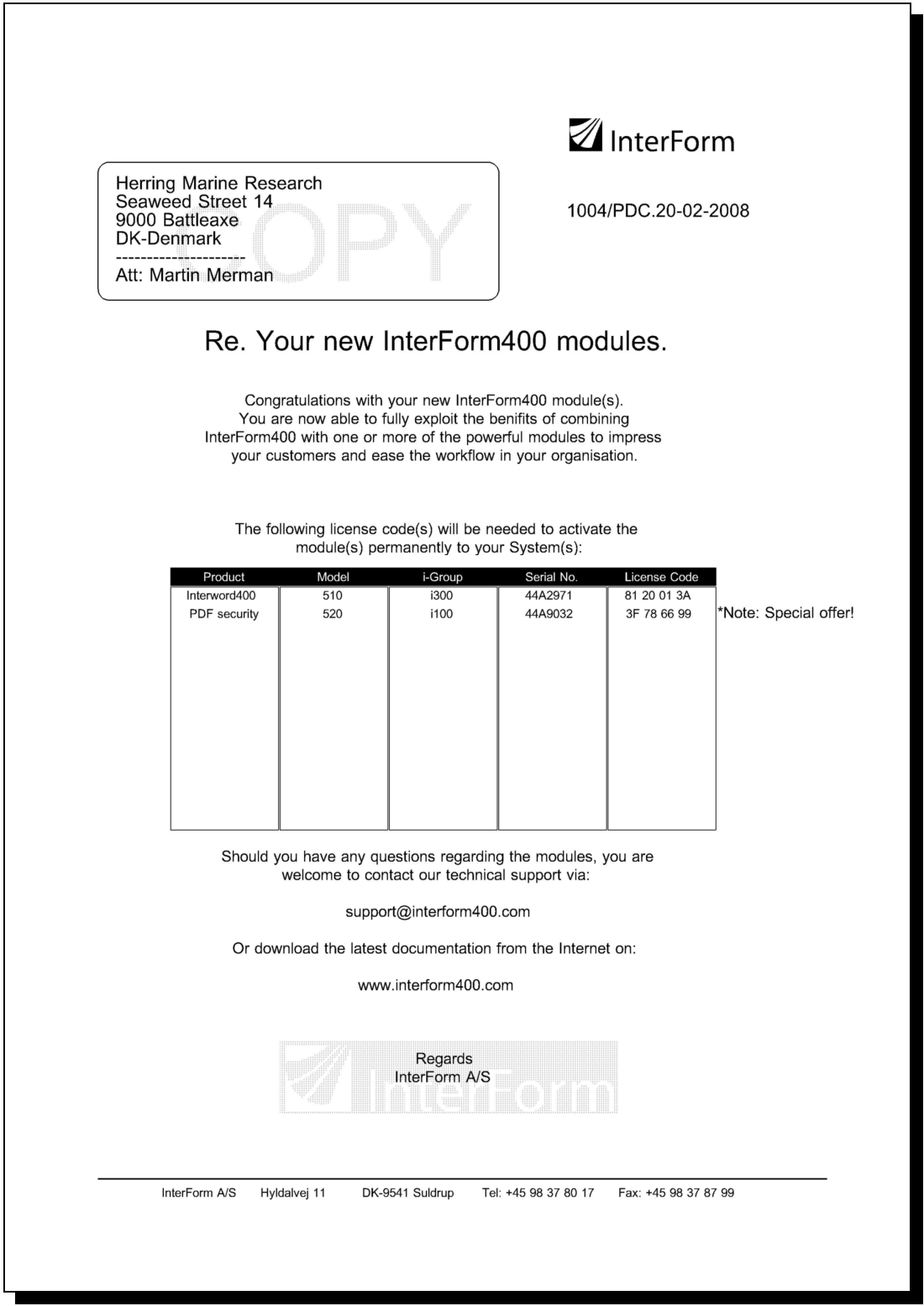
You can start by printing the overlay IF400DEMO if you like to know how the final result will appear.
Please abstract from the fact that it is not a piece of design artwork. We have concentrated mainly on using as many features of the system as possible.
Step 1. Making a Work Copy of the Overlay IF400DEMO
In order to keep the original sample we should first make a copy of the overlays to work with. To prevent the changes we make to be overwritten by future updates of the SAMPLE file-set, we will do the changes in our TEST file-set.
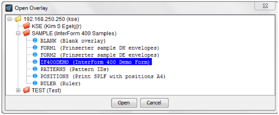
To do that you start up the graphical designer and select the open overlay icon on the upper left:

Select the IF400DEMO overlay and click open:
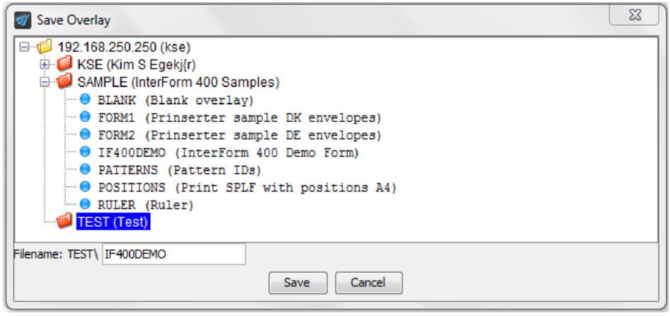
Now select ‘File’ and ‘Save as’ to save a copy of this overlay into the TEST file set. First click on ‘TEST’ and then the save icon.
Step 2. Make a Test Print of the Overlay+Spool Data
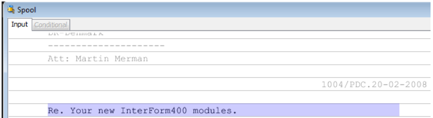
Before we start changing things we will make a printout of the overlay so we know what we have to begin with. To do that we also need to find a copy of the corresponding spooled file.
Click this icon in the top right to view all output queues with one or more spooled files:

Select the output queue APF3812/AFC_INPUT1:
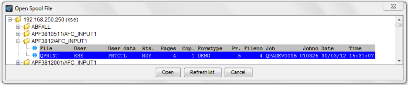
and open the QPRINT spooled file with form type DEMO. If you cannot find the output queue and/or the spooled file you can create in this manner from the green screen with selection:
12. Service functions followed by 1. Create Demo Spool Entry.
You can decide how to divide the rightmost of the screen with this drop down. Select the ‘Place windows vertically’ to view both the original spooled file and the merged result:
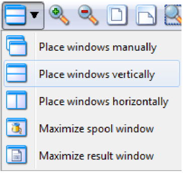
You can also preview the result by pressing the rightmost icons in the top:

In the next sections we will start to re-design the overlay.
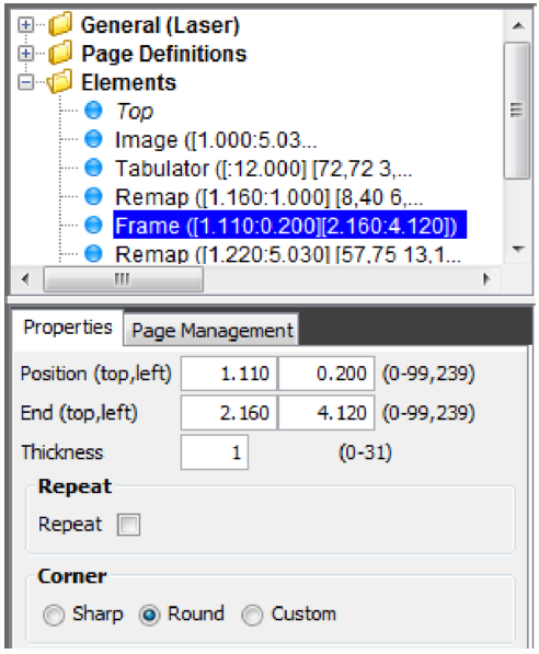
Step 3. Adding Round Corners to the Address Field
The first thing we want to do with our overlay is to make round corners on the address field frame. To do that we simply click the Frame element and change the Corner setting from ‘Sharp’ to ‘Round’ like below:
Step 4. Edit Subject Text
Now we will change the appearance of the subject header text (Re. Your new...). We therefore click on the element after which we want to insert the new element:
Now we click the tabulator element on the left:

to add our first element.
Then drag with the left mouse button pressed around the text to be changed like below:
In the lower right corner of the designer we can see which lines and positions we have marked:

Finally we click in the result view to place the distance from the left where this should be placed. In this case we want to center the text around 4 inches from the left. After this the tabulator is added. Now we can change the properties for the tabulator. Select the ‘Formatting’ tab:
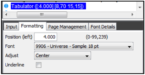
We can fine adjust the distance from the left to exactly 4 inches if needed. Also the font is set to 9906 and we chose to center the text around the 4 inch reference.
Step 5. Formatting the body text
We now want to format the body text to print centered with a proportional spaced font. We use the same procedure as in the previous section, and we therefore click on the previous tabulator element we added and click the tabulator element on the left:
Then select the text in the spooled file (Line 18-26, position 8-80) with the left mouse button and click in the result view to place the tabulator. Finally we adjust the position and font:
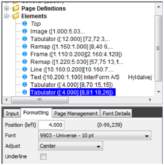
Again we define a safety margin by stating 80 for maximum position. We select a 10 point Univers font for the text.
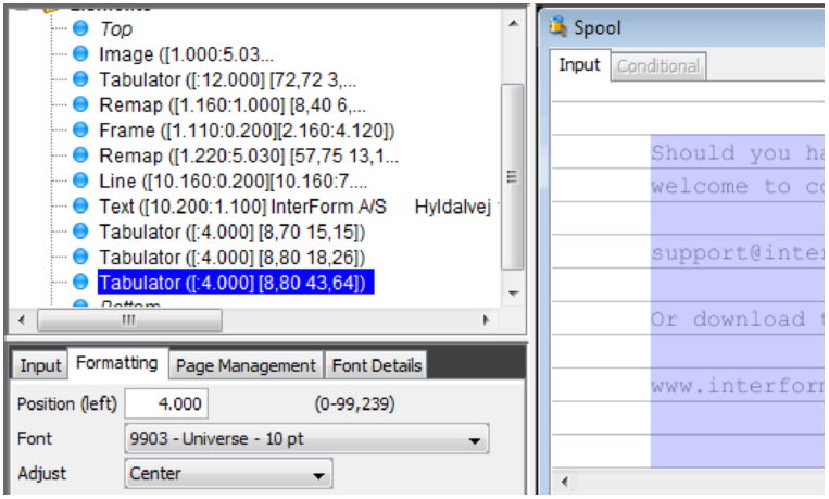
Another Tabulator is inserted for the lines 43-64 also covering positions 8-80:
(Which means from ‘Should you have....’ and onwards).
Step 6. Making Equal Distance Between Column Headers
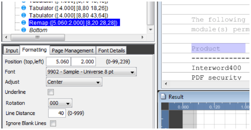
We now want to Format the column headers in the middle of the page (Model, P-Group...) in intervals of 1 inch. As we want to adjust the vertical position as well we will use the Remap Window element, which look like this:

We add the remaps after the last tabulator. Like the tabulator you add a remap window by clicking the element type on the left, drag over the spooled file text in the Input view and finally clicking the destination in the Result view and finally changing the properties of the element.
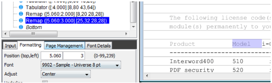
First the ‘Product’ header text is remapped:
We remap a few extra characters to handle if the ‘Product’ text should change a bit in the future.
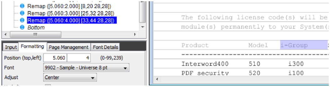
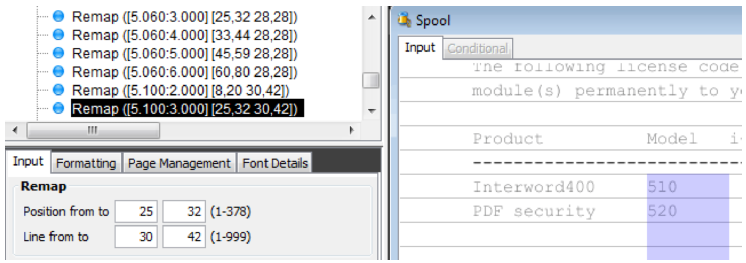
We also remap the ‘Model’ text in the spooled file:
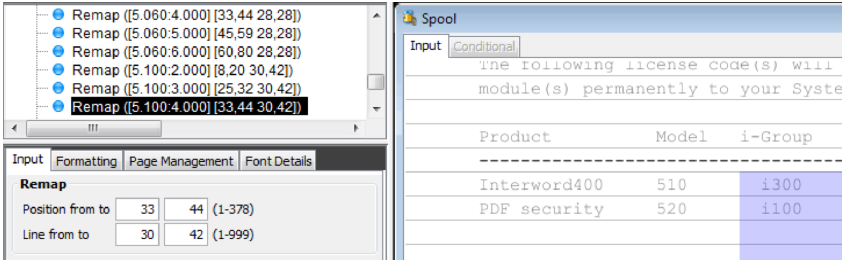
We proceed with column header “i-Group”:
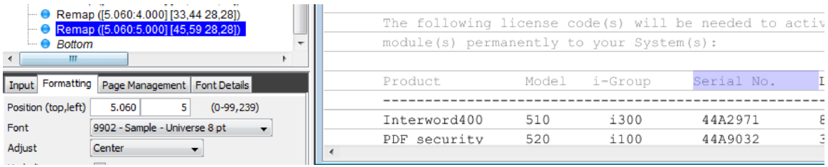
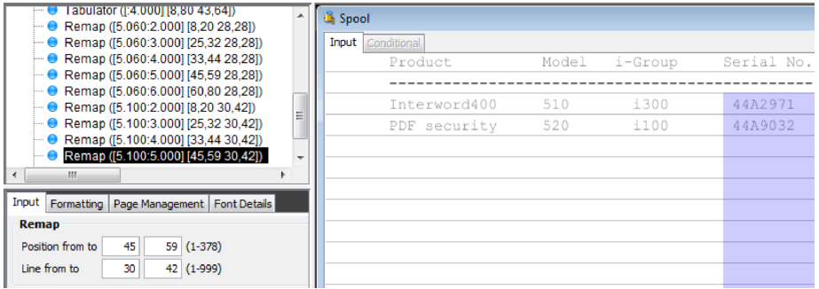
- and the “Serial No.” header:
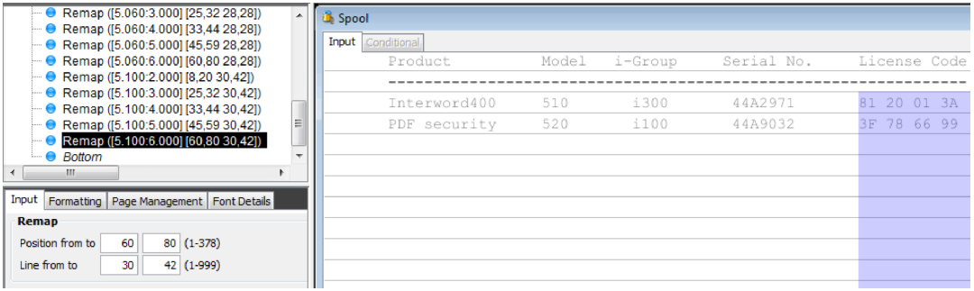
- and finally the “License Code” header:
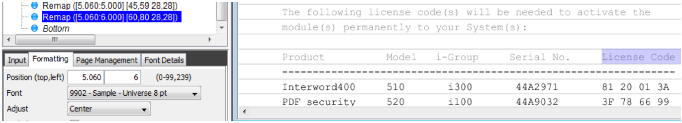
Now the relevant area in the Result view should look like this:
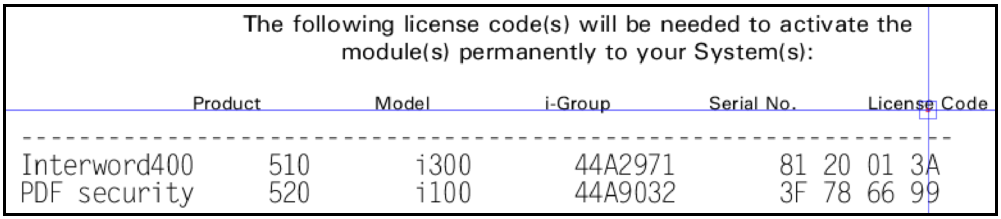
The blue mark is the reference for the last remap window.
Step 7. Making Equal Distance between Item Line Columns
We now want to perform the same actions for the item-line columns below the dotted line. As the horizontal positions of the item line columns are identical to the column headers, we can copy the elements for the headers and just correct the vertical position (from upper edge) and the input line numbers.
We copy the elements by clicking the first remap, holding down the <Shift> key and then clicking on the last remap inserted above and then use the clipboard options ‘Copy’, click the Bottom of the element list and then ‘Paste’:
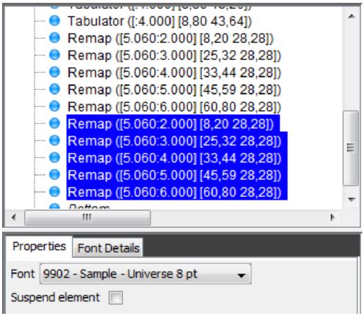
While all the elements are all marked (grouped) we can move them all simply by dragging one of the grouped elements to the new position in the Result View. In this case we drag the elements down 40 pels (1/6 of an inch):
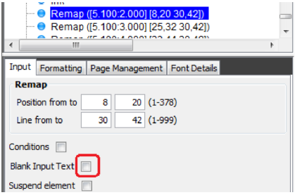
All the marked remaps are referring to line 28, but they should refer to all the detail lines (30-42) instead. So we need to edit each of the remaps. This might be a problem if this default setting is activated: (Double click remap and tabulator elements to update input)
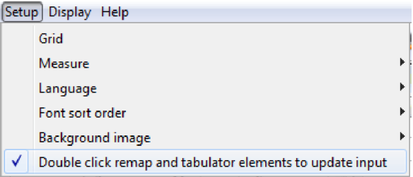
This option is default activated to prevent the user from inadvertently change any remap and or tabulator. So in order to change the remap window elements you can either disable this option or start the coming changes by double clicking the remap window element.
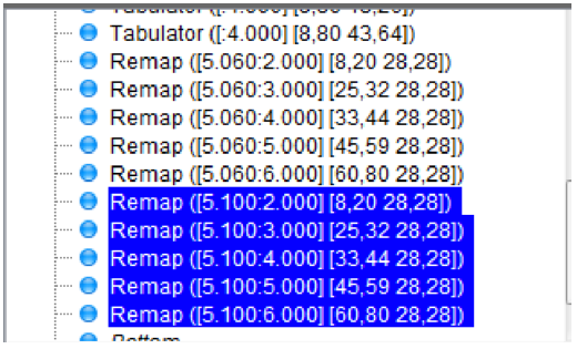
Each of the marked remap window elements is now changed to select lines 30-42 instead of line 28. (Notice a double clicked remap turns black when editing is allowed). You can change them by either dragging in the Input view or be typing the new line interval in the Input tab of each element.
Notice, that we need to disable the ‘Blank input text’ option on the first column as this information will need to remain in the spooled file, so a later call to a conditioned overlay can ‘see’ the original spooled file text:
Step 8. Defining the Column Headers White on Black
Now we would like to make the column headers appear with white text on a black background.
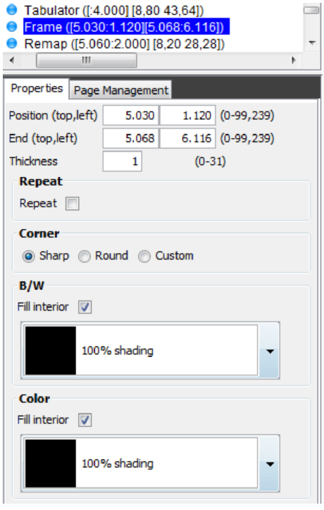
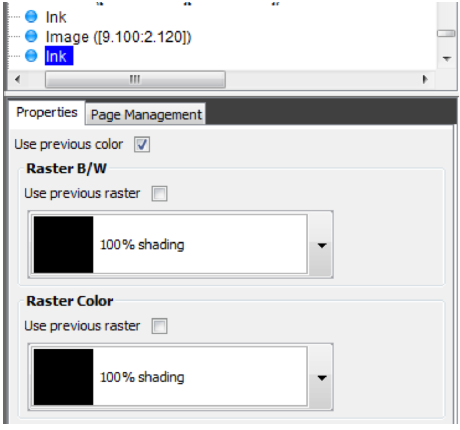
First we will need to define a black box, which is created as a frame with black filling. It is very important that the frame is defined in a sequence before the text in order to place it as a background for the text.
We therefore insert the frame before the remapping of the column header “Product”. We click the tabulator just above in the element list, click the frame element:

Then drag around the headers in the result view to get a frame setting like below. We disable the grid to gain full control of where to position the frame by clicking this icon:

We also mark the shading for both black/white and color output to be 100% black:
Now the frame covers the header line:
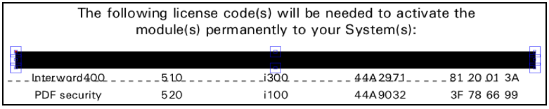
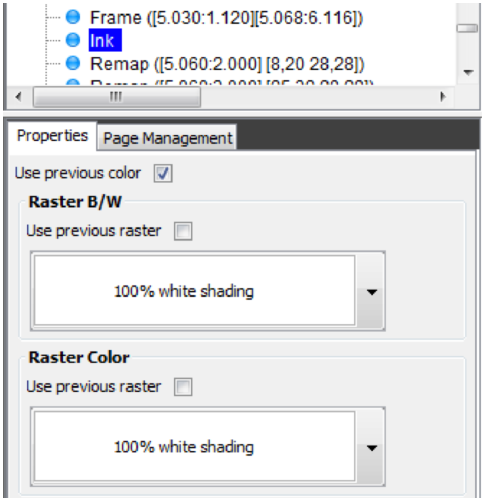
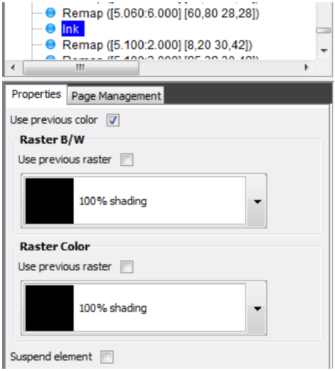
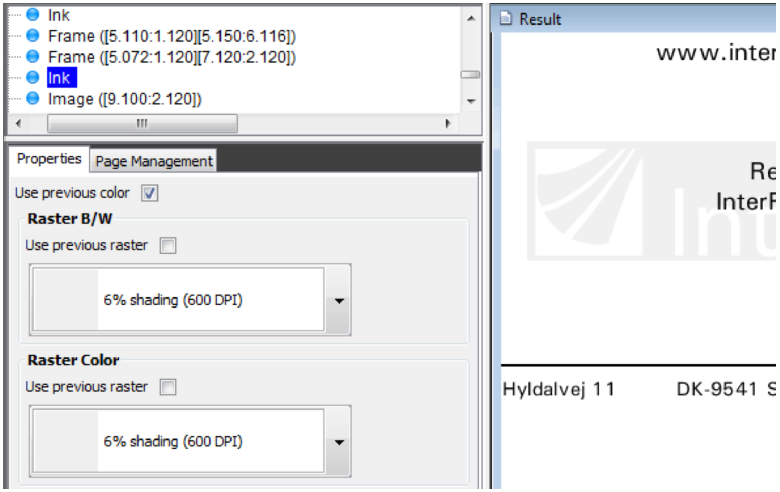
We now insert Ink elements to make the header lines print in white instead of the normal black. First we mark the frame element and click the Ink icon:

Then we change the Ink setting to use white for both black/white and color:
With this change we can see the header lines again, but now the subsequent lines are also printed in white. So we add another Ink line after the remaps of the header lines to print the rest in black: (Both in black/white and color output)
Step 9. Defining the Item Line Bars
We would now like to exploit the Repetition and Pattern options in the overlay element Frame to make shaded horizontal “bars” to provide a better appearance of the item lines.
We place this definition before the first remapping of an item column i.e. we click on the Ink element above in the element list, click the frame element and drag around the second detail line and setup the properties like below:
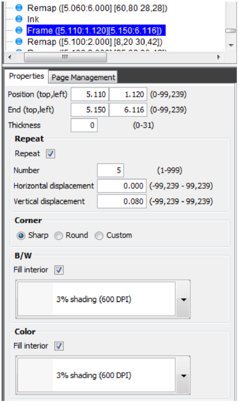
Notice that the height of the fame is 40 pels (5,150 - 5,110), the thickness is set to 0, and the 5 times repetition with a displacement, which is double of the line height and the shading.
Step 10. Defining the 5 Item Column Frames
We now want to define some frames to divide the item lines columns in the spool entry:
We want to place the definition just after the previous definition of the raster frames. So we click that frame element and add a new one: (Dragging around the first column)
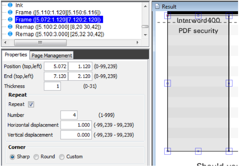
Notice, that the thickness suggested will be that one last used (0), so you need to set it to ‘1'. Also notice the Repeat setting to add frames around all the columns.
Step 11. Defining the logo as a water mark
Instead of a signature we want to place the logo as a watermark in the bottom of the page.
For this we use the logo already used in the top of the overlay, but manipulate it to work as a watermark. We intend to do the following compared to the original logo:
•Reverse it.
•Scale it to double size
•Grayscale it
We define the sequence line for the logo just after the other logo by clicking the first logo element on the element list, clicking the image element on the left:

- and then clicking in the Result Window (on the left above ‘Regards’) to insert it. After that we select the B/W image: DEMOIMAGE and change the settings to reverse and double size (300 DPI):
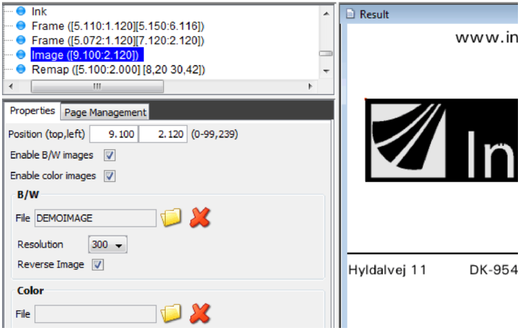
The logo now needs to be dimmed in order to appear as a watermark. For this we change the ink of the image. This is the same procedure we used for printing the column headers white on black.
We insert an Ink element just before the image:
As usual we will need to set the Ink back to black just after the logo:
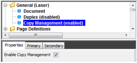
Step 12. Defining the Copy Management
We will now add the text COPY on “page two" copies only. To do this we will first have to enable and configure the copy management.
This is set in the General folder of the overlay:
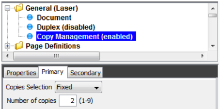
We set the primary number of copies to 2 under the ‘Primary tab’:
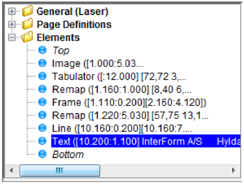
Step 13. Defining the COPY Symbol as Watermark
The intention of the copy sign is to place this information as a watermark in the address field. We can therefore place the text element between the two Ink changes we made for the logo watermark, and thereby exploit the same raster pattern definition.
We click the first Ink element, then the text element on the right:

Then we click in the Result view in the bottom left of the address frame. This inserts the text element as below. We type the text ‘COPY’:
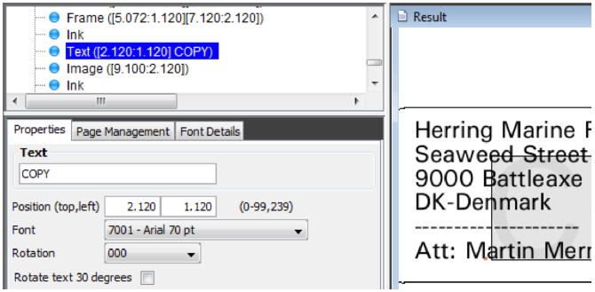
For the font out line we can select one from the existing list. The largest font currently assigned to the system is font ID 2103 with point size 24 (see font list).
We can now choose to use this font, or we can assign a new font ID a larger font.
If you feel comfortable enough with InterForm400 by now, you should try to assign the large font, Go to 80. Administration Menu (either in this session by exiting with F3, or by using another session). Go to section 4. Work with fonts and select 1.Description of additional fonts. Now perform the steps described for defining a resident Printer Font ). Then select ‘File’ and ‘Reload fonts and colors’ in the designer to update the font list.
The text element is to be shown only on copy 2. This is set under the ‘Page management’ tab:
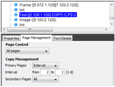
You can see that the element is included on the primary copy 2 only by the indication ‘C:P2-2' in the element list.
Step 14. Defining the Relatively Positioned Sub-form
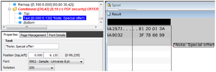
We want to add a condition to the output so that a special text ´*Note: Special offer!’ is added to the right of the detail lines containing the PDF Security module.
This will use one of the more advanced features of the system, generally known as “nested overlays”. To add the call to the other conditioned overlay we first click ‘Bottom’ in the element list to add it as the very last element and the click the ‘conditional element’ on the left:

Now the call to a conditioned overlay is inserted and we can now mark the spooled file line to be considered in the Spool view. We drag over the lines 30-42 with the left mouse button pressed to mark the lines and drag over the positions 8-19 while holding down the right mouse button to mark the positions for the condition. As the compare text we write ‘PDF security’ as written in some lines (case sensitive).
We want to create another overlay to call, so now we create it by pressing this icon on the conditioned element:

Then we are prompted for the name of the new overlay and we type OFFER and press Save.
We can now edit the OFFER overlay by clicking this icon on the conditioned element:

Now we insert a new Text element to the right of the frame as high as possible (as close to the PDF security line as possible - we will move it up later):
Now we go back to the main overlay (IF400DEMO) by pressing the ‘Close overlay’ icon:

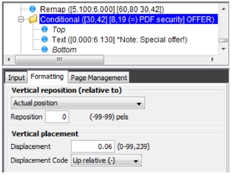
Back in the main overlay we can now edit the conditioned element to reposition it correctly in the vertical direction. We change the vertical placement to minus 0,060:
Step 17. Cleaning the Overlay for Remaining Text
If you printed the overlay at this stage, you will discover that some of the original text used for re-mapping are still visible.
On purpose we have not used “B=Blank after” in all the Remap Window commands, as we have not been sure that we would have needed the text for other purposes.
Instead we have waited to this moment, where we will clean all remaining text by a single command.
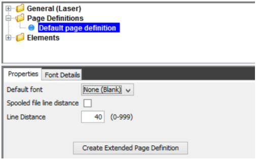
The best and most efficient way is to select NONE as the global font on the header of the overlay:
- alternatively we can do like below:
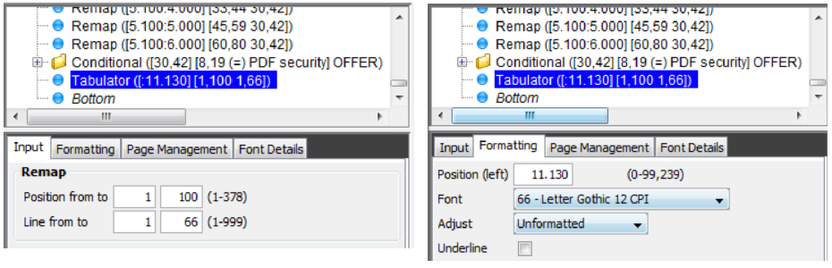
We insert the last element (a tabulator) at the very bottom of the element list:

We then mark all the whole spooled file in the Input View and then click as far right as possible in the Result View:
This will remove the horizontal lines and the original spooled file data in column 1.
Step 18. The Result
Now we can preview the result with the icons on the upper right and print the overlay merged with the spool entry using 3. Merge Spool entry with overlay in the green screen.
If your printout looks like the illustration on the next page, and you understood what went on, you can consider yourself quite familiar with InterForm400.
We have brought you through the heaviest kind of design you will experience with InterForm400.
With this section our intention was to show you the potential of InterForm400 as a Forms Management System and we haven't even talked about the Auto Forms Control features yet.
TROUBLE SHOOTING
Not the result as the following example?
Q Did you use a PCL5 compatible printer?
Q Are you sure all your entries was correct?.
A Try locating the overlay elements which went wrong and check the corresponding overlay definition.
Final print of MYDEMO merged with the sample spool entry. (The illustration is a screenshot of the InterForm400 PCL viewer function:)